Home>Product Information>Precision Mechanical Equipment>Spindle Units>Air Bearing Spindle Units
-
Air Bearing Spindle Units
4.1 Description
For manufacturing equipment of semiconductors and IT devices, it is important to maintain high accuracy flatness of wafers in the grinding process. Therefore, high runout accuracy is required for spindles used in such a process. Especially, NRRO (Non-Repeatable Runout) is required among rotational accuracy. To meet this requirement, we have newly developed air bearings that use porous graphite and obtained high accuracy NRRO.
4.2 Features
- (1)Includes air bearings with porous throttling,these spindle units have high rigidity when compared to other types that utilize bearings with orifice throttling, spontaneous throttling, etc.
- (2)Reusable after slight contact since adhesion does not occur in contact with the rotating axis because of the self-lubricity of graphite.
- (3)High rotational accuracy: NRRO (Non-Repeatable Runout) 0.05 μm or less
- (4)Energy saving effect with air consumption minimized to 40 NL/min or less.
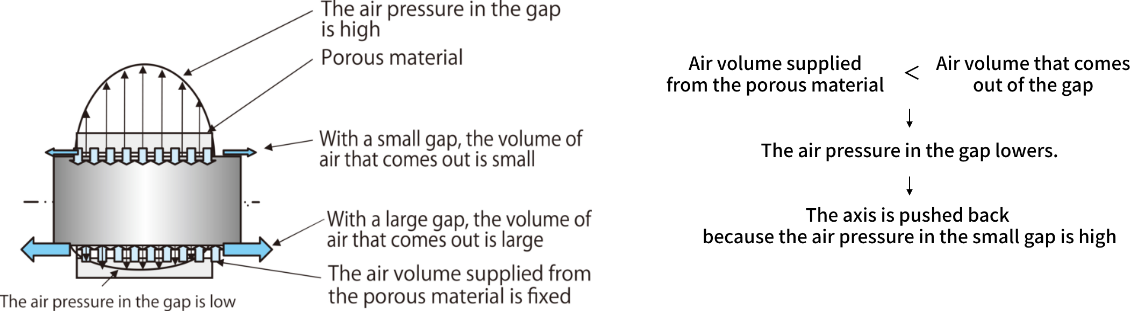
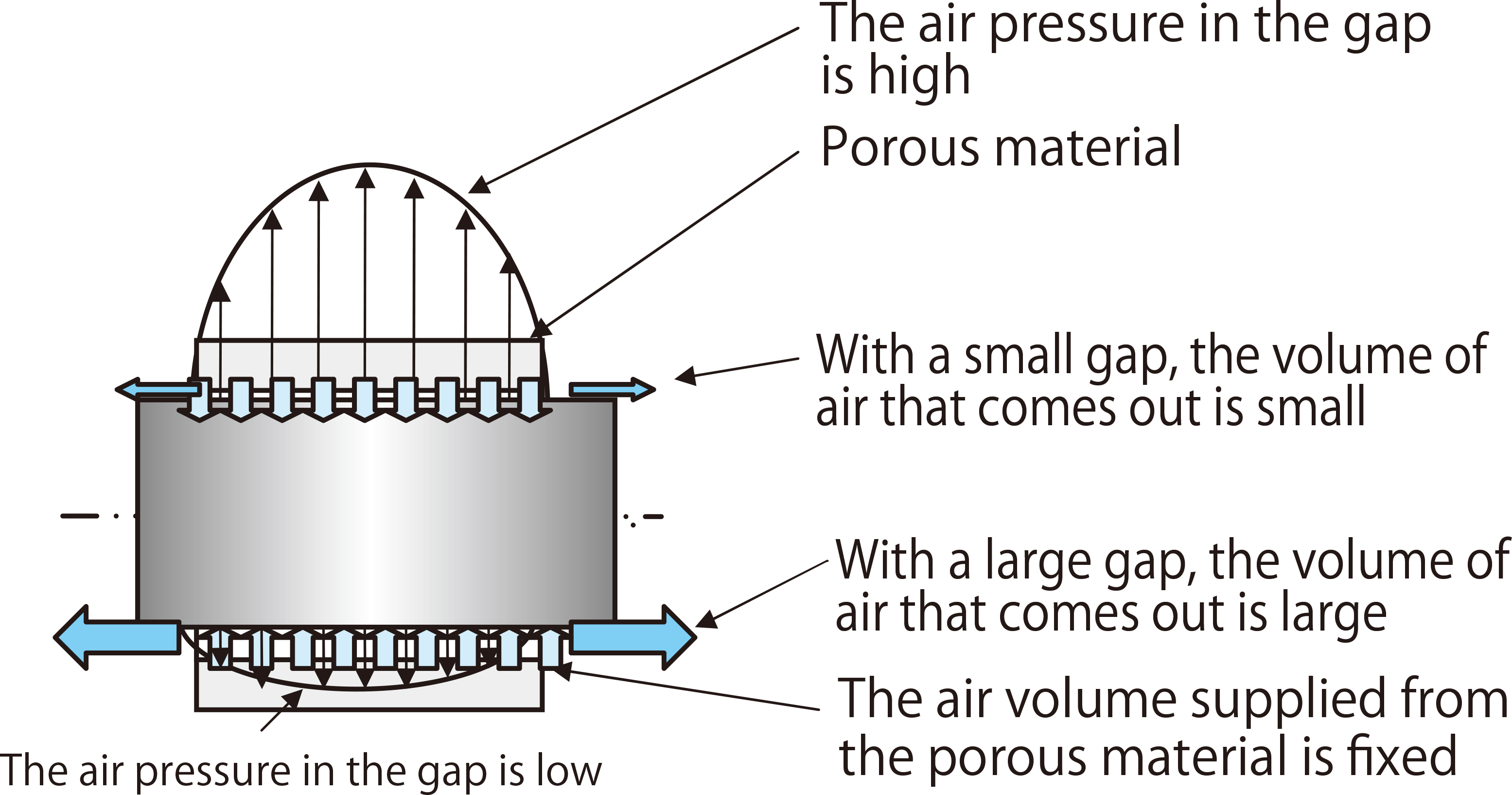
4.3 Principle of Air Bearing
As shown in Fig. 4.1, an air bearing consists of the rotating main axis and a ring or flat plate made of porous graphite to support rotation. Its performance depends on the gap amount between them and the air pressure applied there.
■Fig. 4.1 Principle of Air Bearing

4.4 Characteristics of Radial Bearings
(1)Basic load capacity
The basic load capacity is represented as in the following formula, using the size of the radial bearing attached to the spindle and the supplied air pressure.
Base load capacity = (Bearing internal diameter) x (Bearing width) x (Average pressure)
Average pressure = Supplied air pressure / 2(2)Radial rigidity
The radial rigidity is obtained by dividing the basic load capacity by the gap amount of the bearing as shown in the following formula.
Radial rigidity = Basic load capacity/radial gap (radius)1(3)Example calculation
With bearing internal diameter 70 mm,bearing width 70 mm, bearing gap 0.009 mm and supplied air pressure 0.5 MPa
Base load capacity = 1,225 N
Radial rigidity = 136 N/μm4.5 Characteristics of Axial Bearing
(1)Basic load capacity
The basic load capacity is represented in the following formula, using the size of the axial bearing attached to the spindle and the supplied air pressure. Basic load capacity = ((Bearing outer diameter)2-(Bearing internal diameter)2) / 4 × π ×(Average pressure)1(2)Axial rigidity
The axial rigidity is obtained by dividing the basic load capacity by the gap amount of the bearing as shown in the following formula. Axial rigidity = Basic load capacity / Axial gap (one side)(3)Example calculation
With bearing external diameter 145 mm, bearing internal diameter 75 mm, bearing gap 0.009 mm and supplied air pressure 0.5 MPa Base load capacity = 3,023 N Axial rigidity = 330 N/μm4.6 Structure
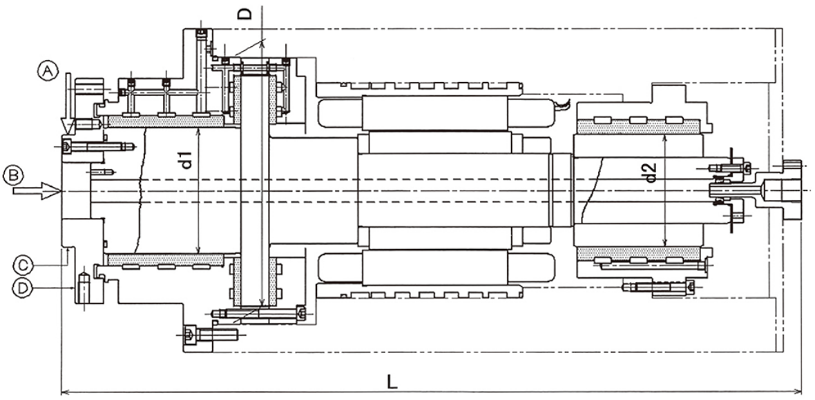
4.7 Main Dimensions and Accuracy
Model
Main dimensions(mm)
Rigidity(N/μm)
Rount(μm)
D
d1
d2
L
A
B
C
D
ASP90
190
90
80
521
90
300
≦2
≦2
ASP70-1
170
70
42
466
50
350
≦2
≦2
Model
Motor
Driver
ASP90
Three phase AC
Commercial inverter
ASP70-1
Three phase AC
Commercial inverter
-
Contact Us
If you have any questions about our products, please contact us.